1 Scope
This standard specifies the definition, classification, requirements, test methods, inspection rules, markings, packaging, transportation, storage, etc. of the conversion-stabilized solar power controller (hereinafter abbreviated as controller) for communications.
This standard applies to solar power controllers that use DC core C conversion and voltage stabilization control technology. It does not apply to grid-connected solar power controllers.
2 normative references
The clauses in the following documents have been adopted as references to this standard. For dated references, subsequent amendments (not including errata content) or revisions do not apply to this standard. However, all parties that have reached an agreement based on this standard are encouraged to study whether the latest versions of these documents can be used. For undated references, the latest version is applicable to this standard.
GB/T 2423.1-2008 Environmental testing for electric and electronic products Part 2: Test methods Test A: Low temperature
GB/T 2423-2008 Environmental testing for electric and electronic products Part 2: Test methods Test B: High temperature
GB/T 2423.3-2006 Environmental testing for electric and electronic products Part 2: Test methods Test Cab: Constant damp heat test
GB/T 2423.10-2008 Environmental testing for electric and electronic products Part 2: Test methods Test Fc: Vibration (sine)
GB/T 2828.1-003 Count Sampling Inspection Procedures Part 1: Batch Inspection Sampling Plans Retrieved by Acceptance Quality Limit (AQL)
GB/T 2829-002 Periodic Inspection Count Sampling Procedures and Tables (Applicable to Process Stability Testing)
YD/T 731-008 Communication High Frequency Switch Rectifier
Technical Requirements and Test Methods for Lightning Protection of YD/T 944 Communication Power Supply Equipment
YD/T 983-1998 Electromagnetic Compatibility Limits and Test Methods for Communication Power Equipment
YD/T 1058-2007 High Frequency Switching Power System for Communication
YD/T 1363.3-005 Central Office of Power Supply, Air Conditioning and Environment Monitoring and Management Systems (Part 3) Part 3: Front-end Smart Device Protocol
YD/T 1363.4-005 Communication Bureau (Station) Power, Air Conditioning and Environment Centralized Monitoring and Management System Part 4: Test Methods
3 Definitions
The following terms and definitions apply to this standard.
3.1
Maximum Power Point Tracking
Under the DC voltage regulation mode, the controller uses a set of power comparison circuits set at the input of the system to automatically track the maximum power operating point of the solar cell when the load requires high power output, so that the system can reach the maximum output power.
3.2
Switching Regulator Solar Power Controller Converting Mode Solar Power Controller
Through the DC heart C conversion voltage regulator circuit, so that the system has a voltage regulator output function of the solar power controller.
3.3
Solar Power Converter Module Solar Power Converter Module
High-frequency switching technology is used to convert the output of the solar array to a parallel DC-DC converter module that is suitable for load use and for the DC power required to charge the battery pack.
3.4
Solar Power Conversion Module Rated Input Voltage Rated Input Voltage of Solar Power Converter Module
The input voltage reference value of the solar power conversion module is similar to the maximum power point voltage value of the matched solar cell array under the standard operating conditions.
4 product categories
4.1 Product composition
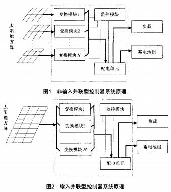
The controller consists of one or more solar energy power conversion modules (hereinafter referred to as conversion modules), monitoring units, power distribution units, etc. The main components are shown in FIGS. 1 and 2 .
4.2 Product Series
4.2.1 DC output voltage nominal value
The nominal value of the DC output voltage: 48V, 24V
4.2.2 DC Output Current Rating
4.2.2.1 The rated output current value of the converter module
The rated output current of the converter module is: 10A, 25A. 30A, 50A, 100A0
4.2.2.2 Controller's rated output current value:
The rated output current of the controller is: 10A, 20A, 30A, 50A1 60A, 100A, 150A, 200A, 300A, 500A.
Note: After negotiating with the manufacturer, the user can produce products other than the above series of values.
4.2.3 Transformer Rated Input Voltage The rated input voltage of the converter module is: 34V, 68V, 136V, 204V, 272V.
Note: After negotiating with the manufacturer, the user can produce products other than the following series of values.
5 requirements
5.1 Environmental Conditions
5.1.1 Storage temperature
-0°C to +70°C
5.1.2 Operating Temperature
Type I: -15°C to +45°C.
Type II: -0°C to +55°C.
5.1.3 Relative Humidity
Working relative humidity: ≤ 90%, no condensation;
Storage relative humidity: ≤95%, no condensation.
5.1.4 Atmospheric pressure
86kPa-106kPa.
5.1.5 Vibration
The controller should be able to withstand frequency of 10Hz-55Hz, amplitude of 0.35mm to sine sweep frequency vibration.
Note: When the product is working outside the following conditions, the manufacturer and user agree on the technical conditions.
5.2 Controller Input Voltage Range
The controller input voltage should be able to work properly when the input voltage of the converter is within 75%-125% of the rated input voltage of the converter module.
5.3 Controller Output Voltage Range
When the converter module outputs rated current, its DC output voltage should be continuously adjustable by the monitoring unit between 90% and 120% of its nominal output voltage.
5.4 Transformation Module
5.4.1 Load Effect (Load Regulation)
The difference between the DC output voltage and the output voltage setting under different load conditions should not exceed ±0.5% of the output voltage setting value.
5.4.2 Source Effect
The difference between the DC output voltage and the output voltage setting under different input voltage conditions should not exceed ±0.1% of the output voltage setting value.
5.4.3 Regulator accuracy
Different input voltages and loads are combined. The difference between the DC output voltage and the output voltage setting under various conditions should not exceed ±0.6% of the output voltage setting value.
5.4.4 Temperature coefficient
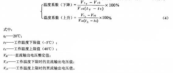
Relative to the ambient temperature of 20°C, the difference between the DC output voltage and the output voltage setting value for each temperature change of 1°C should not exceed ±0.02% of the output voltage setting value.
5.4.5 Load Effect Recovery Time (Dynamic Response)
The recovery time after a change in the DC output voltage caused by a step change (abrupt change) in the load should not exceed 200 ps, ​​and the overshoot should not exceed ±5% of the output voltage setting value.
Note: The recovery time refers to the period when the DC output voltage variation rises above the regulation accuracy and resumes to less than or equal to and no longer exceeds the regulation accuracy.
5.4.6 Switching Overshoot Range
The maximum peak value of the DC output voltage change caused by the switch must not exceed ±5% of the DC output voltage setting.
5.4.7 Startup Inrush Current (Inrush Current)
The input inrush current due to start-up should not be greater than 150% of the maximum steady-state input current peak at rated input voltage.
5.4.8 Soft Start Time
The soft-start time (the time from start to DC output voltage climbs to the nominal value) can be determined according to the user's requirements, generally 3s-10s.
5.4.9 Noise Voltage
5.4.9.1 Telephone noise weight noise
The phone weighted noise voltage at the output of the transform module should not exceed 2 mV.
5.4.9.2 Peak-to-peak noise voltage
The peak-to-peak noise voltage in the (O-2O) MHz band at the output of the converter module should not exceed 200 mV.
5.4.10 Parallel Operation (Homogeneous Load) Performance
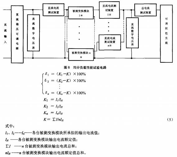
Multiple conversion modules should be capable of parallel output. The input parallel conversion module should be capable of load sharing. The average load current of each module is within 50% to 100% of the rated current. The load imbalance degree of each module should not be changed. Greater than ±5%.
5.5 Controller Efficiency
The efficiency of the controller should meet the requirements of Table 1.

5.6 Maximum Power Tracking Function
The controller should have a maximum power tracking function. When the battery charging voltage does not reach the predetermined charging voltage, the solar cell array can always work near its maximum power point; the solar power supply system access controller power output should be greater than without There is any controller for the output power of solar powered systems.
5.7 sleep function
The controller formed by the input parallel converter module should have a dormancy function: when the average load current of the converter module is less than the current value of the shutdown module set by the monitoring, it should be able to close part of the conversion module; when the load current increases to the monitoring setting When the current value of the module is turned on, the controller should be able to open the closed conversion module; the controller with the dormancy function should enable the module to rotate and avoid long-term high-load operation of some modules.
5.8 No-load power consumption
The input power of the controller at no load shall not exceed 1% of its rated output power.
5.9 Battery Management Functions
The controller should have the following battery management functions:
a) The controller should be capable of temperature compensation of the battery charging voltage, the compensation coefficient adjustment range is (a 7-0) mV / °C / monomer;
b) The controller should be able to charge the battery current limit, the current limit value should be adjustable;
c) The controller shall have the remaining battery charge calculation function;
d) The controller shall have automatic conversion function for charging and floating charge of the battery;
e) The controller shall have a battery over-discharge protection function. When the battery discharge voltage reaches a preset voltage value, the load is turned off to prevent the battery from being damaged due to over-discharge; when the battery voltage recovers to a preset recovery voltage value, The load should be automatically switched back on.
5.10 DC Distribution Unit Voltage Drop
The voltage drop of the DC power distribution unit of the controller should not exceed 500mV (when the ambient temperature is 20°C).
5.11 Interface Requirements for DC Power Distribution Units
5.11.1 The DC power distribution unit shall be provided with a suitable number of load shunts. Each load shunt shall be equipped with fuses or circuit breakers of suitable capacity.
5.11.2 The battery terminals shall be equipped with fuses or circuit breakers of appropriate capacity. The total capacity of the fuses or circuit breakers of all battery terminals shall not be less than 125% of the total rated output current of the controller.
5.11.3 The DC power distribution unit of the controller with a rated output current greater than 100 A should leave an input interface for the backup DC power supply. Its capacity should not be less than the rated output current of the controller.
5.12 Monitoring Function
The monitoring unit of the controller should have the following functions:
a) Real-time monitoring of the working status of the power supply system;
b) Collect and store operating parameters of the power supply system; alarm records can be refreshed at any time; alarm information should continue to be saved under system power off conditions, and the number of stored items should be no less than 100;
C) It shall be able to provide external monitoring interfaces. The monitoring interface protocol shall comply with the provisions of YD/T 1363.3-005:
One by one telemetry: controller input voltage, controller input current, battery voltage, battery charge and discharge current, battery temperature, load current, controller output current;
One-to-one remote signaling: battery over/under voltage alarm, DC output overcurrent alarm, fuse/circuit breaker alarm, controller operation status and fault;
One by one remote control: switch machine state transitions.
5.13 display function
The controller should be able to display: battery voltage, battery charge and discharge current, controller input voltage/current, load current, solar cell cumulative power generation (optional), load cumulative power (optional), battery temperature, battery Over/under voltage alarms, fuse/circuit breaker alarms, load cutoff alarms, and conversion module failures.
5.14 Protection Features
5.14.1 Input Overvoltage Protection
When the input voltage of the controller is higher than the input overvoltage protection value, the controller shall be capable of shutdown protection; the input overvoltage protection value shall not be lower than 125% of the rated input voltage.
When the input voltage is lower than the input undervoltage protection value, the controller should be capable of derating or shutdown protection; the input undervoltage protection value should not exceed 75% of the rated input voltage.
When the input voltage returns to normal, the controller block should resume normal operation.
5.14.2 Output Overvoltage Protection
When the controller output voltage is too high, it should be able to automatically alarm and shutdown protection. After troubleshooting, it should be able to resume work manually or automatically.
When the controller output voltage is too low, it should be able to automatically alarm, after troubleshooting, it should be able to automatically resume work.
5.14.3 Output Current Limit or Output Power Limit Protection
The controller shall have output current limit or power limit function. When the output current reaches the output current limit value, the controller shall enter the current limit state, and the output current shall not continue to increase; the controller shall enter when the output power reaches the output limit power value. In the limited power state, its output power does not continue to increase.
The controller's output current limit value should be within 10% to 110% of its rated current, and the output power limit value should not be less than the rated output power.
5.14.4 Output Overcurrent and Short Circuit Protection
The controller shall have the function of automatic over-current protection and short-circuit protection. After over-current or short-circuit fault removal, it shall be able to resume normal operation automatically or manually.
5.14.5 Input Reverse Protection
The controller should have input reverse polarity protection and should not be damaged when the input polarity is reversed.
5.14.6 Reverse discharge protection of battery
The controller should have a protection function to prevent the reverse discharge of the battery pack through the solar module.
5.14.7 Fuse protection
The battery and load shunts of the DC power distribution unit should be fitted with fuses or circuit breakers of suitable capacity.
5.14.8 Over temperature protection
When the operating temperature of the controller exceeds the over-temperature protection point, the output or exit should be automatically derated; when the temperature drops to the recovery point, the controller should be able to automatically resume normal output.
5.15 Alarm Performance
The system shall be able to automatically issue corresponding acousto-optic alarms while the various protection functions are in motion. The system shall transmit the alarm signals to the near-end and remote monitoring devices through the communication interface. Some alarms may send the alarm signals through corresponding communication interfaces. To the alarm device outside the machine, the alarm signal sent should be able to distinguish the category of the fault.
5.16 Electromagnetic Compatibility
5.16.1 Conduction disturbance limit
The conduction turbulence limit of the controller shall meet the requirements of Table 2A in YD/T 983-1998.
5.16.2 Radiated disturbance limits
The controller's radiation disturbance limit should meet the requirements of Table 4A in YD/T 983-1998.
5.16.3 Immunity
The immunity to the surface of the controller housing is: electrostatic discharge immunity, radiation electromagnetic field immunity.
Immunity to the controller's DC output port includes: electrical fast transient burst immunity, and conducted disturbance immunity of the RF field.
The immunity to the controller's DC input ports includes: electrical fast transient burst immunity, conductive field induced conductive disturbance immunity, surge (shock) immunity.
The controller shall meet the requirements of Table 9 in YD/T 983-1998 during or after the above various immunity tests.
5.17 Security Performance
5.17.1 Insulation resistance
When the ambient temperature is 15°C to 35°C, the relative humidity is 90%, and the test voltage is 500V DC, the following requirements shall be met:
a) The insulation resistance between each independent circuit and ground (ie metal frame) is not less than 10MΩ;
b) The insulation resistance between the circuits without electrical contact is not less than 10 MΩ.
5.17.2 Electrical strength
For a controller with rated input voltage less than or equal to 100V, the output circuit and input circuit shall be capable of withstanding 50Hz to earth, and the effective value is 500V AC voltage (leakage current ≤ 30mA) or 710V DC voltage equivalent to its peak value for 1min, with no hits. Wear and arc-free phenomenon.
For controllers with a rated input voltage greater than 100V, each circuit between the independent circuit and the ground and between which there is no electrical contact shall be capable of withstanding the rated voltage of a withstand voltage alternating voltage of 50 Hz at a voltage amplitude of the insulation test of Table 2. Or use a test voltage of 1.4 times the voltage rating of the withstand voltage rating of the insulation test in Table 2. For 1 min, there should be no breakdown or arcing.

5.17.3 Protective Earthing
Protective grounding points should have obvious signs.
The resistance of the enclosure and all accessible uncharged metal parts and protective earth points shall not exceed 0.1Ω.
5.18 lightning protection requirements
The input of the controller should be equipped with surge protection device, which should meet the requirements of YD/T9.
5.19 Acoustic noise
Acoustic noise should not exceed 60dB (A).
5.20 Reliability Index
The mean time between failures (MTBF) ≥ 5×10⁴h.
6 test methods
6.1 Test environment conditions
Unless otherwise specified, the test shall be conducted under standard atmospheric conditions. The standard atmospheric conditions are:
- ambient temperature: 15 °C ~ 35 °C;
- Relative humidity: 25%-75%;
- Atmospheric pressure: 86kPa-106kPa.
6.2 Controller Input Voltage Range Test
The test is carried out according to the following steps:
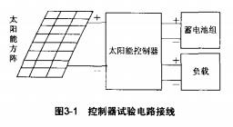
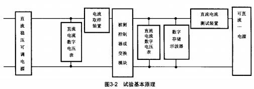
—— Connect the test circuit according to Figure 3-1, and connect the corresponding instrument according to Figure 3-2, adjust the load current to 50% of the rated value, and then use the DC output voltage value as the setting value;
——Adjust the adjustable DC power supply, make the input voltage 125% of the rated value, the DC output voltage is the factory setting value, the load current is the rated value, check the controller should work properly;
——Adjust the adjustable DC power supply, make the input voltage 75% of the rated value, the DC output voltage is the factory setting value, the load current is the rated value, check the controller should work normally.
6.3 Controller Output Voltage Range Test
The test is carried out according to the following steps:
—— Connect the test circuit according to Figure 3-1 and connect the corresponding instrument according to Figure 3-2.
- Start the tested controller, adjust the input voltage to the rated value, the DC output voltage to the factory setting value, and the load current to 50% of the rated value;
——Adjust the DC input voltage to 75% of the rated value, adjust the DC output voltage and load, observe and record the maximum output voltage when the output current reaches the rated value, and the test result shall meet the upper limit of the DC output voltage range specified in Section 5.3;
——Adjust the DC input voltage to 125% of the rated value, adjust the DC output voltage and load, observe and record the minimum output voltage when the output current reaches 5% of the rated value, and the test result should meet the lower limit of the DC output voltage range specified in Section 5.3;
——Check whether the DC output voltage regulation function has manual or continuously adjustable functions controlled by the monitoring unit and meet the requirements of Section 5.3.
6.4 Transformation Module
6.4.1 Load Effect, Source Effect, and Regulation Accuracy Test
The test is carried out according to the following steps:
—— Connect the test circuit according to Figure 3-1 and connect the corresponding instrument according to Figure 3-2.
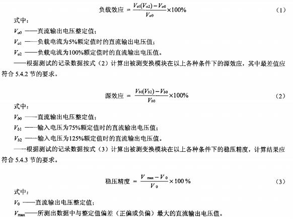
- Start the measured conversion module, adjust the input voltage to the rated value, the DC output voltage to the factory setting value, and the load current to 50% of the rated value;
——Adjust the input voltage to 75%, 125% rating, load current to 5% and 100% rating respectively. Measure and record the DC output voltage under the four states after combination.
—— Calculate the load effect of the tested conversion module under the above conditions according to formula (1) according to the recorded data of the test, where the worst value should meet the requirements of section 5.4.1.
6.4.2 Temperature coefficient test
The test is carried out according to the following steps:
—— Place the measured transformation module in the thermostat, connect the test circuit according to Figure 3-1, and connect the corresponding instrument according to Figure 3-2;
- Start the measured conversion module, adjust the input voltage to the rated value, the DC output voltage to the factory setting value, and the load current to the rated value;
Control the high and low temperature test chamber temperature constant 20 °C ± 1 °C until the measured controller balance stable work, measure and record the DC output voltage value at this time setting value;
- Control the temperature change in the high and low temperature test chamber to the lower limit of the working temperature ± 1 °C (the average change is not more than 1 °C/mm in 5 min), and the constant temperature is 2h until the measured conversion module is balanced and stable, and the interval time is 15min during the constant temperature working time. Record the DC output voltage value of the tested converter module;
——Control the temperature in the high and low temperature test chamber rising from the lower limit (hold for 30 minutes when it rises to 0°C, the average change is not more than 1°C/min within 5min), change it to the working temperature upper limit ±1°C, and keep the constant temperature for 2h to the tested transformation module Balanced and stable work, measure and record the DC output voltage of the tested converter module at intervals of 15min during the constant temperature working time;
——Calculate the temperature coefficient of the measured conversion module when the temperature drops and rises according to formula (4). The calculation result should meet the requirements of section 5.4.4.
6.4.3 Load Effect Recovery Time (Dynamic Response) Test
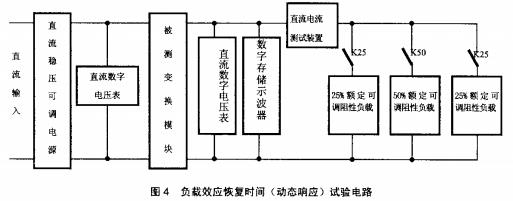
The test is carried out according to the following steps:
- Connect the test circuit according to Figure 4;
- Start the measured conversion module, adjust the input voltage to the rated value, the DC output voltage to the factory setting value, and the load current to 50% of the rated value;
——Mutation of load current causes the load current to change stepwise from 25% of the rated value to 50%→25% and 50%→75%→50%. Observe the DC output of the measured conversion module with the appropriate range of the digital storage oscilloscope. The time-varying waveform of the voltage, the voltage amplitude variation, the overshoot, and the recovery time are calculated. The calculation result should meet the requirements of Section 5.4.5.
6.4.4 Switch Overshoot Amplitude Test
The test is carried out according to the following steps:
—— Connect the test circuit according to Figure 3-1 and connect the corresponding instrument according to Figure 3-2.
- Start the measured conversion module, adjust the input voltage to the rated value, the DC output voltage to the factory setting value, and the load current to the rated value as the setting value;
—— Repeatedly operate the switch module under test three times, observe the time-varying waveform of the DC output voltage with the appropriate range of the digital storage oscilloscope, and calculate the overshoot amplitude of the DC output voltage. The maximum value shall meet the requirements of 5.4.6. .
6.4.5 Startup Inrush Current (Inrush Current) Test
The test is carried out according to the following steps:
—— Connect the test circuit according to Figure 3-1 and connect the corresponding instrument according to Figure 3-2.
- Start the measured conversion module, adjust the input voltage to the rated value, the DC output voltage to the factory setting value, the load current to the rated value, turn off the measured conversion module;
- Start the measured conversion module with the storage oscilloscope with the current sampling device to measure the peak value of the input inrush current and the peak value of the input current after the stable operation;
- Repeatedly start the measured transformation module four times, with two intervals of two minutes, and the maximum starting impulse current shall meet the requirements of 5.4.7.
Note: The us-grade inrush current generated by the EMI circuit is not considered.
6.4.6 Soft Start Time Test
The test is carried out according to the following steps:
—— Connect the test circuit according to Figure 3-1 and connect the corresponding instrument according to Figure 3-2.
- Start the measured conversion module, adjust the input voltage to the rated value, the DC output voltage to the factory setting value, the load current to the rated value, and close the tested conversion module;
- Start the measured conversion module with a digital oscilloscope to observe from the start time of the output voltage climb to the steady output process with a digital oscilloscope. Use the time recording device to record the time used in the process. The result should be consistent with Section 5.4.8. Claim.
6.4.7 Noise Voltage Test
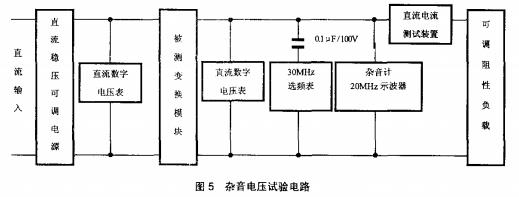
The test is carried out according to the following steps:
—— Connect the test circuit according to Figure 5, and connect the following instruments to the DC output terminals of the measured conversion module according to the test contents: connect the noise meter, test the telephone weighing noise voltage, connect a 20MHz oscilloscope, and measure the peak-to-peak noise voltage;
- Start the measured conversion module, adjust the input voltage to the rated value, the DC output voltage to the factory setting value, and the load current to the rated value;
——Using the weighing weight measurement mode of the phone in the noise meter, select the 600Q or 755 input impedance, and select the appropriate range to read and record the maximum voltage measurement reading of the noise meter, which is the output voltage of the measured conversion module. The value should meet the requirements of section 5.4.9.1;
- Use a 20MHz oscilloscope to select the appropriate range, the oscilloscope scanning speed should be less than 0.5s, read and record the maximum peak-to-peak amplitude displayed by the 20MHz oscilloscope, which is the peak-to-peak noise voltage value at the output of the tested conversion module, which should meet the 5.4 The requirements of section .9.2.
6.4.8 Parallel operation (equal load) performance test
The test is carried out according to the following steps:
——Connect the test circuit according to Figure 6 (the number of tested conversion modules: n couples 3). When the average load performance of the measured conversion module is controlled by the monitoring unit, the measured conversion module should be monitored and controlled by the interface circuit. Unit connection
——Adjust the input voltage of the tested converter module to the rated value;
—— Turn on each of the n measured transformers one by one and adjust the DC output voltage to the factory setting value;
——Adjust the adjustable load so that the total load current is 50% of the rated value, and record the current value of each tested conversion module;
——Adjust the adjustable load so that the total load current is 100% of the rated value, and record the current value of each tested conversion module;
——Calculate the unbalanced degree of load sharing of each unit under test under different output voltage and current according to test record data. The calculation method is shown in formula (5), and the calculation result should meet the requirements in section 5.4.10. .
6.5 Controller Efficiency Test
The controller efficiency test is performed as follows:
—— Connect the test circuit according to Figure 3-1 and connect the corresponding instrument according to Figure 3-2.
——Adjust the input voltage to the rated value, and the output voltage is the output voltage of the conversion module;
- Adjust the load current to 50% and 100% respectively, calculate the DC output power of the tested controller according to the product of the DC output voltage and current, and calculate the DC of the tested controller according to the product of the DC input voltage and current. Input power, according to equation (6) to calculate the efficiency, should meet the requirements of Table 5.5.

6.6 Maximum Power Point Tracking Function
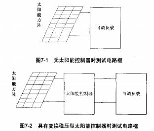
The test is carried out according to the following steps:
- Connect the circuit as shown in Figure 7-1.
- The solar array is directly connected to the resistive load, and the load is adjusted so that the voltage becomes N times the rated output voltage of the controller, N = the voltage of the solar array/68;
- Connect the circuit as shown in Figure 7-2.
——When the input terminal of the controller is connected to the same solar array as mentioned above, and the resistance value of the output connected to the controller is 1/N of the above load, the DC output voltage and the output current of the load side are measured again, and the calculation is available. Load power Po;
- Test results should meet the requirements of section 5.6.
6.7 Dormant function test
The test is carried out according to the following steps:
—— Connect the test circuit according to Figure 3-1 and connect the corresponding instrument according to Figure 3-2.
- When the controller with two or more transformation modules is working normally, adjust the load current, reduce the load current to less than the current value of another switching module, check whether the controller can close a transformation module; Continue to adjust the load current, reduce the load current to less than when closing the current value of the next converter module. Check if the controller can close the next converter module.
- When the controller with two or more transformation modules works normally, adjust the load current and increase the load current to a value higher than the setting value of another transformation module, check whether the controller can start a transformation module. ; Continue to adjust the load current, increase the load current to higher than the set value of the next conversion module to check the controller can open the next conversion module;
—— Periodically check whether the controller with the dormancy function has closed the transformation module whose working time has exceeded the set value, and start the transformation module in hibernation to make it enter the working state;
- The test results shall comply with the provisions of section 5.7 of this standard.
6.8 No-load loss test
The test is carried out according to the following steps:
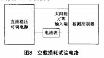
- Connect the test circuit according to Figure 8;
- disconnect the controller (PV) input and load output, DC voltage regulator adjustable power supply connected to the controller battery terminal;
- Calculate the product of the input voltage and the input current to obtain the no-load input power;
- The no-load input power of the controller shall meet the requirements of section 5.8.
6.9 Battery Management Function Check
6.9., Put the temperature sensor into the constant temperature box, the operating point of the voltage of the controller changes with the change of the temperature, the slope of its recording curve should accord with the provision a) of section 5.9.
6.9.2 The battery management function of the inspection system shall be in accordance with the requirements of b), c), d), and e) of section 5.9 through the mode of operation monitoring unit and the actual charging and discharging test method of the battery pack.
6.10 DC power distribution unit voltage drop test
When passing the rated current from the battery terminal of the DC power distribution unit to the load terminal of the DC power distribution unit, measure the voltage drop from the battery terminal to the load terminal and meet the requirements of 5.10; if the ambient temperature is not 20°C, The voltage drop of DC power distribution unit should be calculated according to the following formula (7):

6.11 Interface Requirements Inspection of DC Power Distribution Units
Check the interface of the DC power distribution unit. The result should meet the requirements of Section 5.11.
6.12 Monitoring Function Test
The test is carried out according to the following steps:
——When sending corresponding signals on the remote control float/charging working interface respectively, it should be able to carry out work state transition; when the remote control solar cell square array inputs and outputs the corresponding signals on the work interface, it should be able to carry out work state transition ;
- Check the interface according to the function of the communication protocol according to 11.1 of YD/T 1363.4-2005;
- The result should meet the requirements of Section 5.11.
6.13 Display Function Test
Check if the controller can display the relevant parameter quantities required by section 5.13.
6.14 Protection function test
6.14.1 Input Overvoltage Protection
The test is carried out according to the following steps:
—— Connect the test circuit according to Figure 3-1 and connect the corresponding instrument according to Figure 3-2.
——Adjust the adjustable resistive load to the rated value, adjust the voltage of the DC voltage regulator adjustable power supply to overvoltage protection point, the controller should be able to automatically alarm and protect, after the voltage drops to the set value, it should be automatic or Manual restoration work;
——Adjust the adjustable resistive load to the rated value, adjust the voltage of the DC voltage regulator adjustable power supply below the undervoltage limit power point, the controller should work with derating, adjust the voltage of the DC voltage regulator adjustable power supply to off. Below the protection point of the controller, it shall be automatically protected and alarmed; the voltage shall be recalled to the recovery point, and the controller shall be able to recover automatically.
6.14.2 Output Overvoltage Protection
The test is carried out according to the following steps:
—— Connect the test circuit according to Figure 3-1 and connect the corresponding instrument according to Figure 3-2.
- The battery is replaced by a DC voltage regulator and the adjustable resistive load is adjusted to the rated value. The voltage of the DC voltage adjustable power supply is adjusted to the overvoltage protection point. The controller should automatically alarm and protect the voltage. After the set value, it should be able to resume work manually;
——Adjust the adjustable resistive load to the rated value, adjust the voltage of the DC voltage regulator adjustable power supply below the undervoltage protection point, and the controller shall alarm;
When the voltage is set back to the recovery point, the controller should automatically return to normal.
6.14.3 Output Current Limit or Output Power Limit Protection Test
The test is carried out according to the following steps:
—— Connect the test circuit according to Figure 3-1 and connect the corresponding instrument according to Figure 3-2.
- Start the measured controller, adjust the input voltage to the rated value, the DC output voltage is the factory setting value, and the load current is 50% of the rated value;
——Adjust the load current to the current limit point or output power to the constant power value, check whether the controller meets the requirements of Section 5.14.3;
——Reducing the load current back to the rated value range, check whether the controller can reply. The result should meet the requirements of section 5.14.3.
6.14.4 Output Overcurrent and Short Circuit Protection Test
The test is carried out according to the following steps:
—— Connect the test circuit according to Figure 3-1 and connect the corresponding instrument according to Figure 3-2.
- Switch on adjustable DC power supply, start the system, make the controller over-current or short circuit;
- Test results should meet the requirements of Section 5.14.4.
6.14.5 Input Reverse Protection
The test is carried out according to the following steps:
—— Connect the test circuit according to Figure 3-1 and connect the corresponding instrument according to Figure 3-2.
- Reversing the polarity of the load, solar module, and battery, respectively;
- Test results should meet the requirements of Section 5.14.5.
6.14.6 Battery Reverse Discharge Protection
The test is carried out according to the following steps:
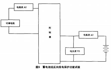
- Connect the test circuit according to Figure 9;
——Adjust the adjustable resistance and check whether there is current flowing through A2. If A2 current reading is 0, the controller has reverse discharge protection function;
- Test results should meet the requirements of Section 5.14.6.
6.14.7 Fuse protection
The test is carried out according to the following steps:
—— Connect the test circuit according to Figure 3-1 and connect the corresponding instrument according to Figure 3-2.
- simulated fuse failure;
- Test results should meet the requirements of Section 5.14.7.
6.14.8 Over temperature protection
The simulated ambient temperature exceeds the system setpoint. Check that the controller is operating according to the requirements of Section 5.14.8 and meet the requirements of Section 5.14.8.
6.15 Complaints performance test
The test is carried out according to the following steps:
—— Connect the test circuit according to Figure 3-1 and connect the corresponding instrument according to Figure 3-2.
- Switch on the DC voltage regulator adjustable power supply, start the system, simulate the fault or put the controller into protection state;
- Test results should meet the requirements of Section 5.15.
6.16 Electromagnetic Compatibility Test
The test method shall be carried out in accordance with the requirements of 5.5 in YD/T 983-1998 and shall comply with the requirements of Section 5.16.
6.17 Safety Performance Test
6.17.1 Insulation resistance test
With the test voltage of DC 500V of insulation resistance tester, the circuit between each independent circuit of the tested controller and the ground and no electrical connection shall be tested. The test result shall meet the requirements of Section 5.17.1.
6.17.2 Electrical strength test
The test is carried out according to the following steps:
- Use a pressure tester to test the controller against electrical strength;
- The tested controller shall perform the insulation resistance test and meet the requirements before conducting the test of the electrical strength;
——Test voltage: For controllers with an input voltage less than or equal to 100V, the test voltage of the output circuit and input circuit to earth is 500V, 50Hz AC voltage or 710V DC voltage equivalent to its peak value; for input voltage greater than 100V The controller, between each independent circuit and the ground, between the circuits without electrical connection shall be able to withstand tests with a frequency of 50 Hz and a voltage amplitude of the test level of the insulation test of Table 2 or with a test voltage of the insulation test of Table 2. 1.4 times the DC voltage of the rated AC withstand voltage;
- Test duration: The test voltage gradually increases from less than half the maximum amplitude, and it lasts 1 min when the specified voltage value is reached;
- Test results should meet the requirements of Section 5.17.2.
6.17.3 Protective earthing test
The test is carried out according to the following steps:
- Visual inspection of grounding points, tandem conductors, etc. shall meet the requirements of Section 5.17.3;
- The system under test should be completely disconnected from the input circuit, output circuit, monitoring equipment and all external circuits;
——Using digital micro-ohmmeters, Kelvin bridges and other micro-resistance measuring instruments, measuring the connection method (two-wire or four-wire) according to the micro-resistance measuring instrument, and measuring the main connection terminal of the measuring line to the main protection grounding terminal; the other end of the measuring line The metal parts that may be touched on the outer surface of the door (plate) that can be moved before and after, and the handles, buttons, key locks, etc. of the door and the door;
- Read the resistance value of the connection between the main protective grounding terminal and each measurement point in order from the micro resistance measuring instrument and meet the requirements of Section 5.17.3.
6.18 lightning protection test
Lightning protection test according to YD/T 944, the results should meet the requirements of 5.18.
6.19 Audio Noise Test
The test is carried out according to the following steps:
- The measured noise at the test site, ie the noise floor, is not less than 7dB;
——Connect the test circuit according to Figure 3-1 and connect the corresponding instrument according to Figure 3-2. Start the tested controller. Adjust the DC input voltage within the controller input voltage range of Section 5.2. Adjust the load current to the rated value. ;
- Use a sound level meter to measure at a distance of 1m from the front of the device under test and 1/2 of the height of the device. The results of the measurement shall meet the requirements of 5.19.
6.20 Reliability Test
The reliability test is performed according to section 5.4.9 of YD/T 731-008.
6.21 Environmental Test
6.21.1 Low Temperature Storage Test
Test method according to GB/T 2423.1-2008 "test Ab". The tested controller has no packaging, no power, and no battery. test
The temperature is (-40 ± 3) °C and the duration of the test is 16h. After the test, the requirements in Table 3 should be met.
6.21.2 Low temperature working test
Test method according to GB/T 2423.1-2008 "Test Ad" carried out. The tested controller has no packaging.è¯•éªŒæ¸©åº¦ä¸ºâ… åž‹ï¼ˆ-15±2)℃,Ⅱ型(-30±2)℃,试验æŒç»æ—¶é—´ä¸º2h,试验åŽåº”符åˆè¡¨3ä¸ç›¸å…³æ€§èƒ½æŒ‡æ ‡è¦æ±‚。
6.21.3高温贮å˜è¯•éªŒ
试验方法按GB/T 2423.2-008ä¸â€œè¯•éªŒBbâ€è¿›è¡Œã€‚è¢«æµ‹æŽ§åˆ¶å™¨æ— åŒ…è£…ä¸å«ç”µæ± ã€ä¸é€šç”µã€‚试验温度为(70±2)℃,连ç»è¯•éªŒæ—¶é—´ä¸º16h。试验åŽåº”符åˆè¡¨3ä¸ç›¸å…³æ€§èƒ½æŒ‡æ ‡è¦æ±‚。
6.21.4高温工作试验
试验方法按GB/T 2423.2-2008ä¸â€œè¯•éªŒBdâ€è¿›è¡Œã€‚è¢«æµ‹æŽ§åˆ¶å™¨æ— åŒ…è£…ã€‚è¯•éªŒæ¸©åº¦ä¸ºâ… åž‹(45±2)℃,â…¡åž‹(55±2)℃,试验æŒç»æ—¶é—´ä¸º2h,试验åŽåº”符åˆè¡¨3ä¸ç›¸å…³æ€§èƒ½æŒ‡æ ‡è¦æ±‚。
6.21.5æ’定湿çƒè¯•éªŒ
试验方法按GB/T 2423.3-006ä¸â€œè¯•éªŒCbâ€çš„è¦æ±‚è¿›è¡Œã€‚è¢«æµ‹æŽ§åˆ¶å™¨æ— åŒ…è£…ã€‚è¯•éªŒæ¸©åº¦ä¸ºï¼ˆ40±2℃),相对湿度(93±3)%,试验æŒç»æ—¶é—´ä¸º2h,试验åŽåº”符åˆè¡¨3ä¸ç›¸å…³æ€§èƒ½æŒ‡æ ‡è¦æ±‚。
6.21.6振动试验(æ£å¼¦ï¼‰
被测控制器在ä¸å¸¦åŒ…装的æ¡ä»¶ä¸‹æŒ‰GB/T 2423.10-008F。的è¦æ±‚与方法进行试验,频率为10Hz-55Hz,振幅为0.35mm,周期时间为æ¯æ ¹è½´çº¿æ–¹å‘30min。试验åŽåº”符åˆè¡¨3ä¸ç›¸å…³æ€§èƒ½æŒ‡æ ‡è¦æ±‚。
7检验规则
7.1检验分类
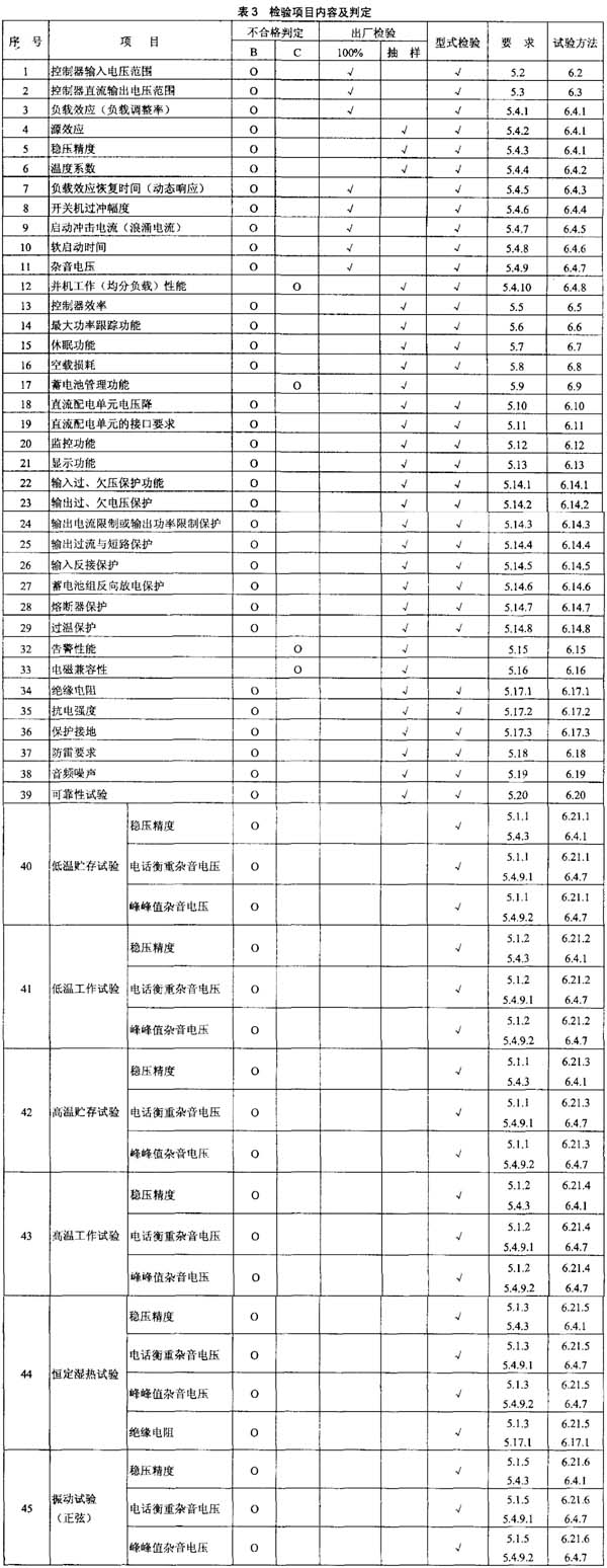
产å“检验分为出厂检验和型å¼æ£€éªŒã€‚出厂检验分100%检验和抽检两ç§ï¼Œå¯æ ¹æ®æƒ…况任选一ç§ï¼Œæ£€éªŒåˆæ ¼åŽå¡«å†™æ£€éªŒè®°å½•å¹¶å‘ç»™åˆæ ¼è¯æ–¹èƒ½å‡ºåŽ‚。
7.2出厂检验
7.2.1 100%检验
æ¯å°æŽ§åˆ¶å™¨å‡ºåŽ‚æ—¶å‡è¿›è¡Œè€åŒ–åŽçš„å‡ºåŽ‚æ£€éªŒã€‚æœ‰ä¸€é¡¹æ€§èƒ½æŒ‡æ ‡ä¸ç¬¦åˆè¦æ±‚,å³ä¸ºä¸åˆæ ¼ï¼Œåº”返修å¤è¯•ã€‚å¤è¯•å†ä¸åˆæ ¼ï¼Œåˆ™ä¸èƒ½å‘ç»™åˆæ ¼è¯ã€‚
100%检验的检验项目ã€è¦æ±‚åŠè¯•éªŒæ–¹æ³•è§è¡¨3。
7.2.2æŠ½æ ·æ£€éªŒ

7.3åž‹å¼æ£€éªŒ
åž‹å¼æ£€éªŒæŒ‰å‘¨æœŸè¿›è¡Œï¼Œä¸€èˆ¬1年进行一次,具有下列情况之一的å‡éœ€åšåž‹å¼æ£€éªŒï¼š
a)产å“åœäº§ä¸€ä¸ªå‘¨æœŸä»¥ä¸Šåˆæ¢å¤ç”Ÿäº§ï¼›
b)转厂生产å†è¯•åˆ¶å®šåž‹ï¼›
c)æ£å¼ç”Ÿäº§åŽï¼Œå¦‚结构ã€ææ–™ã€å·¥è‰ºæœ‰è¾ƒå¤§æ”¹å˜ï¼›
d)产å“投产å‰ç¾å®šæˆ–è´¨é‡ç›‘ç£æœºæž„æ出。
åž‹å¼æ£€éªŒæŒ‰GB/T 2829-2002进行,采用判别水平IIçš„ä¸€æ¬¡æŠ½æ ·æ–¹æ¡ˆï¼Œäº§å“è´¨é‡ä»¥ä¸åˆæ ¼æ•°è¡¨ç¤ºã€‚产å“çš„ä¸åˆæ ¼ç±»åž‹åˆ†ä¸ºB类和C类,产å“ä¸åˆæ ¼è´¨é‡æ°´å¹³ï¼ˆRQL)è§è¡¨4。

8æ ‡å¿—ã€åŒ…装ã€è¿è¾“和贮å˜
8.1æ ‡å¿—
æ ‡å¿—åº”ç¬¦åˆYD/T 1058-007çš„7.1规定。
8.2包装
包装应符åˆYD/T 1058-007çš„7.2规定。
8.3è¿è¾“
è¿è¾“应符åˆYD/T 1058-007çš„7.3规定。
8.4è´äº¡å˜
è´®å˜åº”符åˆYD/T 1058-2007çš„7.4规定。
It can be equipped with a scrolling display that displays 300-500 words of display content. It can also be equipped with intelligent infrared probe anti-collision device, which can automatically return to work when people or foreign objects are 20-30CM, thus ensuring the safety of vehicles and pedestrians.It can automatically open and close when automatic clutch is cut off. Manually open and close when manual clutch is cut off. The control system has control panel, push button switch, and other requirements. Equipped with wireless remote control.The door body is made of high-quality stainless steel and aluminum alloy profiles, and is hinged by the parallelogram principle. The drive is driven by special motor, worm and worm gear deceleration, and has automatic clutch or manual clutch.
Factory Sliding Retractable Gate,Aluminum Alloy School Sliding Gate,Automatic Electric Single Double Gate,Store Retractable Gate
Shenzhen Hongfa Automatic Door Co., Ltd. , https://www.hfrollershutterdoor.com