1 Introduction
The principle of metal cutting is a technical science to study the laws of metal cutting. The cutting of metal materials is to cut a part of the metal on the workpiece with a tool with higher hardness than the workpiece material, so as to obtain the required shape accuracy, dimensional accuracy and surface quality [1, 2]. Study the metal cutting process rules to improve product quality And the production efficiency is very important, so the principle of metal cutting is the compulsory content of all the basic courses of mechanical engineering in colleges and universities nationwide.
The metal cutting process can be understood as the process in which the cutting layer metal (the metal layer to be cut on the workpiece) is plastically deformed by the pushing of the tool and separated from the workpiece to form the chip. The deformation of the cutting layer metal is the result of the force exerted by the tool. This force is the cutting force. It is one of the important phenomena in the metal cutting process [1-4]. There are many factors affecting the cutting force, and the cutting speed has a relatively high influence on the cutting force. Special rules. In the traditional experiment, the cutting speed is affected by the diameter of the workpiece, resulting in an inconspicuous or even unsatisfactory experimental effect.
This paper intends to use the frequency converter to realize the stepless speed regulation of the machine tool spindle, and then the cutting speed can also be changed steplessly, so that each experiment can get better experimental results.
2 The influence of cutting speed on cutting force
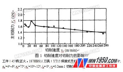
When cutting brittle metal materials (such as gray cast iron, lead brass, etc.), the chips are broken, the plastic deformation is small, and the knife-chip friction is small, so the cutting speed has little effect on the cutting force. However, when cutting plastic metal materials (such as 45 steel, ductile iron, etc.), the effect of cutting speed on cutting force is shown in Fig. 1. Generally, the cutting force is divided into three component forces in the x, y, and z directions, wherein the component force in the z direction is the main cutting force, and is represented by Fc. It can be seen from Fig. 1 that Fc exhibits a trend of "decrease-increase-decrease" with the increase of cutting speed vc, and this relationship of Fc-vc is also called "hump curve", which is mainly affected by built-up edge. Caused by the impact. In the cutting of plastic materials, when vc is not high and continuous chips can be formed, a hard block with a triangular cross section is often stuck near the cutting edge of the tool, which is called built-up edge. Its height Hb is affected by vc, and the higher the Hb, the actual front The larger the angle, the smaller the cutting force. When vc<20m/min, with the increase of vc, Hb gradually increased, so that Fc gradually decreased. Near vc=20m/min, Hb rose to the highest, making Fc appear extremely small; at 20m/min

3 Problems in the experiment
The curve in Fig. 1 is generally obtained by a turning experiment, but the vc in turning is calculated by the formula (1).

Where d--workpiece diameter (mm);
N-- Spindle speed (r/min).
It can be known from formula (1) that d is getting smaller and smaller in the experiment, so that vc is affected, and the diameter of the workpiece cannot be too small, otherwise vibration will occur due to insufficient rigidity. n is a series of speeds achieved by adjusting the transmission gear on the machine tool by the speed handle. For example, the CA6140 lathe spindle has 10, 12.5, 16, 20, 25, 32, 40, 50, 63, 80, 100, 125, 160, 200, 250, 320, 400, 450, 500, 560, 710, 900, 1120. And 1400 r / min a total of 24 speed. The extreme points in the hump curve only appear in the case of vc<40~50m/min. Figure 2 shows the effect of the workpiece diameter on the cutting speed. It is not difficult to see that when the gear is matched by the step diameter, when it is affected by the diameter of the workpiece, when it is 20m/min
| Previous page | 1 | 2 | 3 | Next page |
LED spike lights are ideal
for illuminating flower beds and borders. They come in a variety of finishes,
wattage and heights. Very versatile and great for all kinds of garden features.
LED spike lights are the most flexible style of light and can be used for a
variety of situations. Place a spike light close to steps to light them up.
Installing a purpose designed step light in to brick work is a lot of work and
a spike light can offer a cheaper and just as effective solution. With a fully
adjustable head for tilt and rotation they are ideal to illuminate trees and
items of interest in the garden. They can also be used near water features and
place a colored lamp in the fitting for a more dramatic lighting effect. Many
have glare shield attachments to reduce direct glare from the lamp source.
Led Garden Spike Light,Led Spike Light,Outdoor Spike Light,Plastic Spike Light
ZHONGSHAN G-LIGHTS LIGHTING CO., LTD. , https://www.glightsled.com