Abstract: The finite element software ANSYS/Workbench is used to establish a three-dimensional finite element model of steel structure twisted joints. By comparing the stress distribution of the twisted and non-twisted joints under external load, temperature load and thermal coupling, respectively Directional strain distribution, to determine the influence and change of the force before and after the node is twisted. The results show that in the absence of temperature field, the twisting can effectively reduce the maximum load of the beam-column joint and make the plastic hinge at the lower node move outward. In the case of fire, the steel beam-column temperature curve changes in a gradient nonlinearly, and the heating rate of the crowned steel frame is slightly slower than that of the non-twisted steel frame. When an external load is applied, the action of the weir is weakened, and the upper flange beam-column joint will produce a plastic hinge earlier than the joint between the weir and the lower flange.
Key words: steel structure; finite element analysis; fire; twisted joint; thermo-mechanical coupling
Nodes are often the main damaged part in earthquakes, so they are often used for node protection, but they are often accompanied by fires in earthquakes. In practice, no matter what force is applied, twisting will protect the nodes. However, after comparing the three cases of external load, heat and heat-force coupling, the results were not the same.
At present, there are not many researches on the beam-column joints of steel structures, but the main direction is the mechanical problem of thermal coupling on common beam-column joints [1-2], or the mechanics of non-fired conditions under twisting conditions. Problem [3], the lack of research on the internal stress state of steel structures at high temperatures, especially under thermo-mechanical coupling, and whether the addition or not affects the fire resistance of the nodes, these problems are unavoidable. Question.
In this paper, the simulation sequence is carried out according to the thermo-mechanical coupling → only external force → thermal stress, but the order of argument is in the order of force application, that is, only external force → only temperature stress → thermo-force coupling.
1 Selection of structural materials at high temperatures
1.1 Thermal physical parameters of steel selection
1) Thermal expansion coefficient: Take the thermal expansion coefficient of steel at room temperature specified in European Steel Structure Specification EC 3 [4], ie 1.4×10⁻⁵ °C-1.
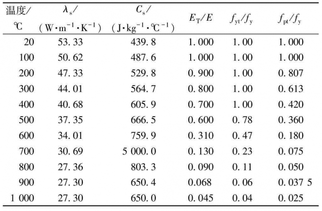
2) Thermal conductivity: The thermal conductivity calculation formulas of EC 3 and EC 4 [5] are used. The specific transformation is shown in Table 1.
3) Specific heat capacity: In order to make the simulation more accurate, the specific heat capacity Cs is the value according to the temperature change in EC 3 and EC 4 . The specific values ​​are shown in Table 1.
4) Density: The density of steel Ïs changes little when changing temperature, taking 7 850 kg/m3.
1.2 Mechanical properties of ordinary structural steel at high temperature
1) Poisson's ratio: The value ranges from 0.27 to 0.30 at room temperature, and μs=0.3.
2) Proportional relationship of elastic modulus reduction coefficient: EC 3 graphically shows the initial elastic modulus reduction coefficient of ordinary structural steel under high temperature conditions. This article is based on this. See Table 1 for details.
3) Strength ratio reduction factor: ECCS [6] graphically shows the strength reduction factor of ordinary steel structures at high temperatures, which is based on this paper. See Table 1 for details.
Table 1 Values ​​of steel materials at different temperatures
Temperature/°Cλs/(W·m-1·K-1)Cs/(J·kg-1·°C-1)ET/Efyt/fyfpt/fy2053 33439 81 0001 001 00010050 62487 61 0001 001 00020047 33529 80 9001 000 80730044 01564 70 8001 000 61340040 68605 90 7001 000 42050037 35666 50 6000 780 36060034 01759 90 3100 470 18070030 695000 00 1300 230 07580027 36803 30 0900 110 05090027 30650 40.0680 060 0375100027 30650 00 0450 040 025
Note: ET is the elastic modulus at high temperature; fyt is the yield strength at high temperature; fyt/fy is the reduction factor of yield strength; fpt/fy is the proportional strength reduction factor.
2 Establishment of finite element model
2.1 finite element calculation model
The model beam and column are H-section, the steel column section is HW400×400×13×21, the steel beam section is HN400×200×8×13, the column height is 3 200 mm, the beam length is 2 600 mm, and the twisted design is The truss beam has a horizontal length of 240 mm and a vertical height of 140 mm. See Figure 1 for details.
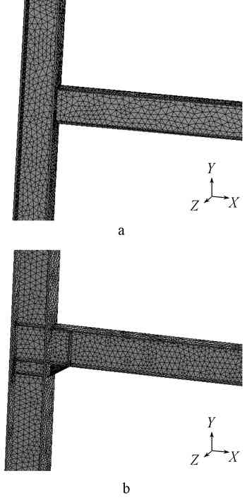
A—normal node; b—credit node.
Figure 1 finite element model
2.2 Establishment of the model under the ANSYS/Workbench platform
1) Selection of unit type: Unlike the traditional classic interface, Workbench automatically selects the unit by calculation results, so this article uses the system default unit.
2) Define engineering data parameters: including expansion coefficient, thermal conductivity, specific heat capacity, density Poisson's ratio, elastic modulus and other corresponding parameters.
3) Meshing: Using tetrahedral meshing, it can save more computing resources and improve the efficiency of meshing without reducing the number and quality of meshes. The grid is subdivided for the twisted part, as shown in Figure 1 and Figure 2.
A—non-twisted node; b—twisted node.
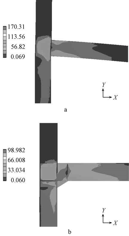
Figure 2 Frontal stress distribution cloud map MPa
2.3 Application of load
2.3.1 Temperature load
The direct fire zone of the non-twisted joint is the inner side and the outer side of the lower floor flange of the steel beam, the sides of the web and the inner side of the steel column. The twisted portion also includes the inside and outside of the twisted flange and the sides of the web of the file. In the thermal analysis, the air temperature rises according to the ISO 834 standard temperature rise curve, where the initial temperature is 20 °C, and the total temperature is calculated to be 2 100 s per 60 s for one load step, and the maximum temperature rises to 865 °C. The conduction mode of air conduction to the steel member is convection heat transfer and radiation heat transfer, and the connection mode is just connected. The overall type of analysis uses transient thermal analysis.
2.3.2 External stress loading
A fixed constraint is applied to the bottom of the column end, and then a load of 100 kN is applied in the negative direction of the Y-axis at the upper end of the steel column, and a load of 50 kN is applied to the negative X-axis direction and the negative Y-axis direction respectively at the right end of the steel beam.
3 finite element calculation results and analysis at room temperature
3.1 Stress cloud analysis of beam-column joints in non-fired state
It can be seen from the equivalent stress cloud diagram of the non-twisted node in Fig. 2a that the stress distribution at the beam-column joint is more concentrated than other locations. From the stress distribution diagram in the positive direction, the stress distribution on the steel beam increases from the center of the beam along the positive and negative directions of the Y-axis, reaching the upper and lower flange nodes of the beam, producing local maximum stress, and the lower wing The stress generated at the edge is greater than the upper flange, both in the maximum and in the radiation range. From the point of view of the column, the equivalent stress distribution is not uniform, mainly distributed in the middle of the column and the vicinity of the beam joint and the lower part of the column, and the maximum stress is generated near the upper and lower flanges of the beam-column joint, with the beam-column contact surface The center of the beam is the origin, the stress is along the negative direction of the X axis, the triangular stress field is formed in the positive and negative directions of the Y axis, and the domain gradient of the stress drop is formed along the negative direction of the X axis.
It can be seen from the equivalent stress cloud diagram of the twisted joint in Fig. 2b that the maximum equivalent stress is generated at the boundary between the flange and the lower flange of the beam. On the steel beam, the center of the beam stiffener is taken as the origin, the equivalent stress increases gently along the positive and negative directions of the Y-axis, and the local stress maximum is generated at the upper and lower flanges, and the stress value at the lower flange is significantly larger than the upper flange. At the office. From the steel column, the equivalent stress is between the two stiffeners in the middle, forming a relatively uniform equivalent stress domain, and radiating from the X-axis and Y-axis from the maximum local stress. The lower part of the stiffener below the column, the equivalent stress distribution is more uniform, and no local stress concentration effect is produced.
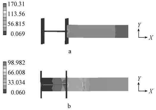
Comparing the bottom stress cloud diagram before and after twisting (Fig. 3), it can be clearly seen that stress concentration occurs at the ordinary non-twisted joint, and the maximum stress is 170.31 MPa at that point, and decreases in the positive direction along the X axis. After the beam-column joints are twisted, the stress at the flange-column joints is greatly reduced. The maximum stress is about 98.98 MPa at the joint between the flange and the column flange, which is only 58% of the maximum stress of the ordinary non-twisted joint. And the stress domain surface at the node is translated in the positive direction of the X-axis on the steel beam and in the negative direction of the Z-axis on the steel column, and the stress distribution is more uniform than before the twisting.
A—non-twisted node; b—twisted node.
Figure 3 bottom stress distribution cloud map MPa
3.2 Comparative analysis of stress along different paths
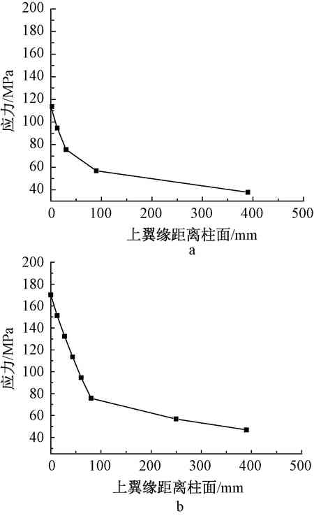
A—upper flange; b—lower flange.
Fig. 4 Stress curve of non-twisted joints
As shown in Fig. 4, in the case of non-twisting, the stress at the upper and lower flanges decreases as the distance from the node increases, and the local maximum stress is generated at the node. Among them, the local maximum stress of the upper flange is 113.56 MPa, and the local maximum stress of the lower flange is 170.31 MPa. From the analysis in the figure, when the structure is carrying too large load, the joint between the steel beam flange and the column flange is likely to break first, and the plastic hinge at the lower flange joint weld is faster than the upper one. Flange. If damage occurs, it is very likely that the sudden brittle failure of the joint occurs in the case where the steel beam and the column are not yielded as a whole, causing serious consequences.
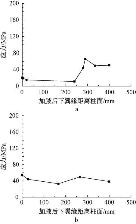
A—upper flange; b—lower flange.
Figure 5 Stress change at the twisted joint
As shown in Fig. 5, in the case of twisting, the stress curve produces an extreme value near the node, wherein the local maximum at the upper flange node is 55.02 MPa, and the local maximum at the lower flange node is 20.05 MPa. In the range of 20 to 240 mm from the node, the upper and lower flanges are more uniform and the change is relatively small. When the distance reaches about 240 mm, the stress at the lower flange suddenly increases, and the maximum local stress is formed at 290 mm, which is 66.08 MPa. This is because after twisting, the lower flange plastic hinge is moved away from the node domain and moved to a distance other than the twist. The upper flange has a local stress maximum of 49.8 MPa at a distance of 260 mm from the cylinder. This is because the stiffener here strengthens and reduces the deflection, which increases the local stiffness and creates local stress concentration. It can be seen from the analysis that if the structure is subjected to excessive external loads, plastic joints will first be created at the twisting, the girders will be deformed, and then a plastic hinge will be produced at the weld between the upper flange and the cylindrical joint. The order of failure is the truss beam joint, the truss beam, and the upper flange node of the beam and column. This form of failure can effectively exert the structural integrity, greatly reduce the possibility of brittle failure, and effectively protect the safety of the lower flange node of the beam and column. Give full play to the role provided by the è…‹ itself.
In summary, it can be seen that the addition or not has a great influence on the force of the beam and column without considering the temperature field. By adding twisting, the maximum stress value can be effectively reduced; by twisting, the stress domain surface can be enlarged and the force in the domain surface can be more even and gentle, and the degree of local concentrated stress can be reduced; the position of the plastic hinge can be moved outward by twisting, Far away from the node, the location of the damage occurs outside the range of the twisting, which satisfies the requirements of the “strong node weak component†in the structural design; by adding the concrete to increase the overall margin, so that the beam is preferentially absorbed when the whole beam is affected by the external force. Destruction to ensure the safety of the overall structure.
4 Analysis of finite element calculation results at high temperature
4.1 Temperature rise of the structure and temperature comparison of the main parts
The air temperature is in accordance with the ISO 834 standard heating curve [7]. The structure heating process is evenly stable, and the temperature does not jump or decrease, which reflects the good thermal conductivity of the steel.
The average temperature of the beam at the joint, the average web temperature of the column and the average web temperature of the web were taken as reference for the comparison of the heating rate. The specific heating time and temperature changes are shown in Fig. 6.
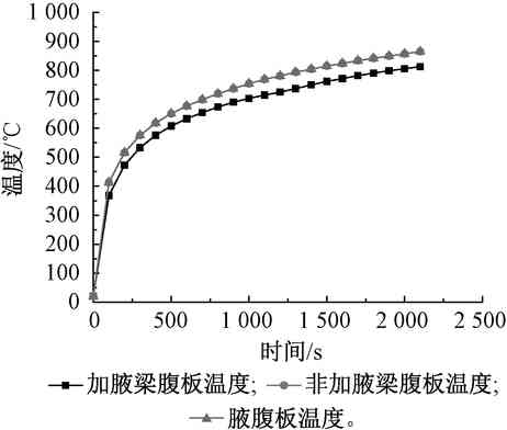
Figure 6 Change in web temperature
Firstly, comparing the two cases of twisting and non-twisting, it can be seen from the data in the figure that the overall temperature rise is relatively flat and uniform. The rate of web temperature rise of the steel beam is almost the same as that of the non-twisted steel beam. The rate of rise is consistent. Using specific data as a reference, at 100, 500, 1 000, 1 500, 2 000 s, the temperature at the time of twisting was 367.8, 607.7, 703.1, 761.8, 805.8 °C, respectively, and the temperature at the time of non-twisting was 413.5, 650.6, respectively. 754.1, 815, 857.4 °C, respectively, the difference is 45.7, 42.9, 51, 53.2, 51.6 °C, although there is a temperature difference, but the difference is small, and relatively stable. This phenomenon may be due to the presence of crucibles and stiffeners. The convection of the air and the radiative heat transfer between the plates are slightly affected by the surface contact, resulting in a difference in the temperature of the directly heated surface, resulting in the heating rate of the twisted steel beam web. The degree is slightly slower than the non-twisted steel beam web.
Comparing the temperature of the beam web and the web of the crucible in the case of twisting, it can be seen that under the same temperature boundary condition, the heating rate of the crucible is faster than the heating rate of the steel beam. At 100, 200, 300, 400, 500 s, the web temperature of the beam is respectively The temperatures of the webs were 367.8, 472.9, 533.1, 576, 607.7 °C, and the web temperatures were 413.1, 516, 575.9, 618.5, 650.7 °C, respectively. This may be due to the fact that 腋 as a direct contact surface is affected by the convective heat transfer of the air, which is greater than the influence of the web at the joint, and the temperature of the web at the joint can be better transmitted to the column that is not directly heated and has a lower temperature. Half, thus causing a temperature difference. It can also be seen from the final temperature results after 2 100 s that the final temperature of the web is higher than the final temperature of the steel webs of 864.8 °C and 813.1 °C, respectively.
4.2 Comparison of equivalent stress analysis results under temperature load only
In order to make the results more obvious, the structural equivalent stress distribution cloud diagram under temperature load is taken after heating for 2 100 s, as shown in Fig. 7.
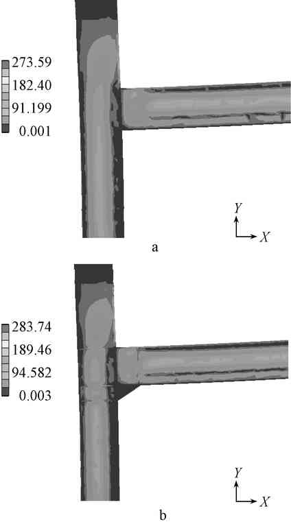
A—non-twisted node; b—twisted node.
Figure 7 Stress distribution cloud map (2 100 s) MPa
Taking the outer flange of the bottom of the column as the coordinate origin, the maximum stress distribution at the twisted and non-twisted nodes at 2 100 s appears in the X-axis direction at 67.5, 60 mm from the outer column flange, respectively, 283.7, 273.59 MPa, the maximum stress value after twisting is 3.7% higher than the maximum stress value in the case of non-twisting.
From the perspective of the overall stress distribution, the stress is mainly concentrated at the web of the beam and column, and the flange is minimally affected. From the analysis of the flange of the twisted beam, the direct stress of the lower flange of the beam is extremely small and the distribution is about 16 MPa, the average stress of the upper flange is about 78.5 MPa, and the average stress of the upper flange is 62.5 MPa higher than the average stress of the lower flange. .
As shown in Fig. 7b, the stress at the twisting is extremely small, and the crucible itself does not have much influence on the structural stress distribution.
In summary, it can be seen that the twisting does not reduce the maximum load value of the structure when it is simply subjected to the temperature load, and may even have a negative effect as the case occurs in the simulation of this paper; the stress generated by the temperature is mainly concentrated on the web. Where, the average stress value of the inner fired flange is lower than the outer non-fired portion. This is different from the conventional experience; the twisting itself does not show obvious value under the condition of simple fire load, and it can hardly change the stress distribution at the beam-column joint. Therefore, under the condition of pure fire load, the addition or not has little effect on the structural redundancy.
4.3 Analysis of stress-strain results under thermal-force coupling
In order not to bias the results toward a major factor, thermo-mechanical coupling at the appropriate temperature is chosen for observation and analysis, see Figure 8.
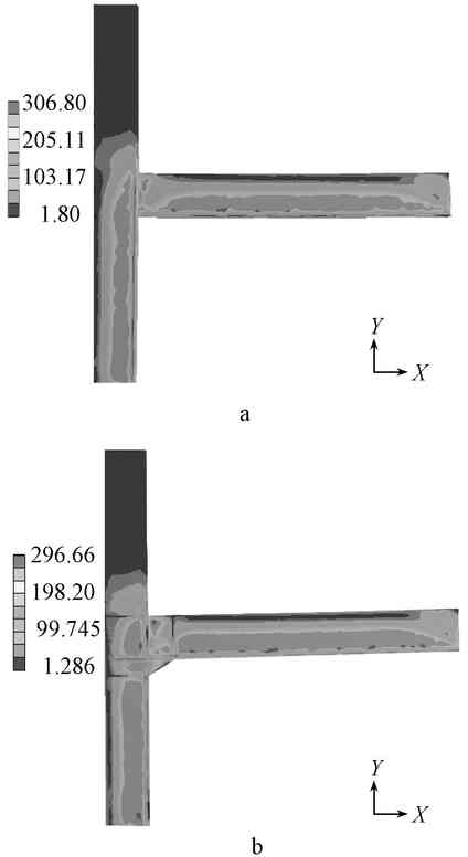
A—non-twisted node; b—twisted node.
Figure 8 Stress distribution cloud map (thermal-force coupling) MPa
In the case of non-twisting, the local maximum stress value at the upper flange beam-column joint is 227 MPa, and the local maximum stress at the lower flange node is 153.3 MPa. The overall maximum stress appears at 56 mm from the cylinder in the middle of the web. Its maximum value is 306.8 MPa. The average stress of the upper flange is 86 MPa, and the average stress of the lower flange of the steel beam is 162 MPa.
In the case of twisting, the local maximum stress at the upper flange beam-column joint is 215 MPa, the maximum stress is reduced by 5.58%, the local maximum stress at the lower flange node is 149 MPa, and the maximum stress is decreased by 2.8%. The overall maximum stress occurs at 49 mm from the upper flange, which is 296.7 MPa, which is 76 mm in the Y-axis direction compared to the non-twisted case. The average stress of the upper flange of the steel beam is 83.3 MPa, and the average stress of the lower flange of the steel beam is 148.9 MPa. The average stress of the flange is 50.6 MPa, and the local maximum stress at the joint with the lower flange is 132.6 MPa.
The twisting under the action of thermal coupling can improve the stress distribution at the joints, especially the stress distribution at the web of the beam and column is more uniform, and the overall maximum stress is reduced. The local maximum stress drop of the upper flange node is more than that of the lower flange, which is caused by the small influence of the twisted joint under the thermal stress on the lower flange. The twisting also causes the maximum stress to move in the positive direction of the X-axis and the Y-axis, away from the lower node of the beam and column, but the è…‹ does not fully exert its function. Therefore, the order of failure may be that the upper flange node of the beam precedes the twisting node, so that brittle failure occurs, which does not meet the structural requirements of the weak member of the strong node.
5 Conclusion
The addition of heat-force coupling is beneficial to the overall structure, especially at the nodes, but at the same time, this part of the enthalpy is only provided to the external load, and the thermal stress is partially affected. Very limited. In the traditional case, under the action of external load, the twisting can effectively prevent brittle failure at the weld joint of the lower flange beam-column joint, and the plastic hinge appears to move outward. However, it can be seen from the simulation of this paper that if the twisting is simultaneously affected by the thermal stress and the external load, brittle fracture is likely to occur, but the position where it occurs becomes the upper flange node. Therefore, it is especially important to protect the nodes, especially the upper flange beam-column joints.
references
[1] CAO Yu-sheng, FENG Guo-ming. Nonlinear analysis of stress response of composite steel frames under high temperature[J].Steel Construction, 2015, 30(4): 92-96.
[2] Fang Tingyong, Zhang Taolin, Lu Ping, et al. Study on Mechanical Properties of Single-Layer Steel Structure Frame under Thermal Coupling[J].Fire Science and Technology, 2008(8): 551-555.
[3] Li Guojun. Finite element analysis of steel nodes before and after twisting[J]. Journal of Shijiazhuang Railway University (Natural Science Edition), 2010, (1): 98-101.
[4] European Committee of Standardization. Eurocode 3: Design of Steel Structures, Part 1.2: Structural Fire Design: ENV 1993-1-2 [S]. Brussels: 2010.
[5] European Committee of Standardization. Eurocode 4: Design of Composite and Concrete Structures, Part 1.2: Structural Fire Design: ENV 1994-1-2 [S]. Brussels: 2010.
[6] European Convention for Construction Steel.European Recommendation for the Fire Safety of Steel Structures[S] .Brussels:2009.
[7] China Engineering Standards Association. Technical Specifications for Fire Protection of Building Steel Structures: CECS 200:2006 [S]. Beijing: China Planning Press, 2006.
NONLINEAR FINITE ELEMENT ANALYSIS OF STRESS REPONSE OF HAUNCHED JOINTS AND NORMAL JOINTS AT HIGH TEMPERATURES
JIANG Liyun LUO Ye LUO Zhiwen
(College of Civil Engineering, Inner Mongolia University of Technology, Hohhot 010051, China)
ABSTRACT: A 3D finite element model of steel structure of haunched joint was constructed by using the finite element software ANSYS Workbench, and the haunching's effects and changes were estimated by comparing the differences between hauched joints and normal joints in distribution rules and distribution changes in each direction Under these three circumstances: external load, temperature load and coupled thermal-mechanical. The results showed that in the non-effect temperature field, hauching could decrease the beam-column joints' maximum stress and then the plastic hinge, which wass in the bottom When the circumstance turned to the high-temperature environment, the steel beam-column's temperature curve was non-linear, and the warming of steel frame with haunching was slightly slower than that of non-haunching. , if the steel frame was added extra external stress, the power of haunching would weaken. Thus, the plastic hinge would appear on top fl Ange beam-column joints faster than that on bottom flange joints.
KEY WORDS:steel structure; finite element analysis; fire; haunched joint; thermal-mechanical coupled
Author: Jiang Liyun, female, born in 1967, master's degree, associate professor.
Email:
6 Blade Ceiling Fan,Six Blades Ceiling Fan,Ceiling Fans With Remote,Six Blade Ceiling Fan
Jiangmen MagicPower Electrical Appliances Co.,Ltd. , https://www.magicpowerfan.com